Noco tech Motor Noco tech Motor

How to Choose the Right Robotic Gear Motor?

Time:2026-10-13 Author:Amelia
0%

Choosing the right Robotic Gear Motor begins with the robot’s real working conditions, not its advertised speed. A small arm moving a camera needs different performance from a mobile robot carrying a heavy battery. Torque, speed, voltage, duty cycle, and gearbox ratio must match the application. Measure the load at the output shaft. Do not rely on estimates alone.

In practical testing, engineers often compare startup torque, continuous torque, noise, heat, and backlash. A motor may lift the load briefly, yet fail after hours of repeated movement. Heat matters. Poor ventilation can shorten lubricant life and weaken magnets. Check the gearbox material, bearing design, shaft diameter, and mounting pattern before ordering. These details can prevent expensive redesigns.

A reliable Robotic Gear Motor should also offer stable performance across changing loads. Encoders can improve position control, but they add cost and wiring complexity. Brushed motors may suit simple prototypes, while brushless options often support longer service life. Neither choice is automatically best. That depends on control requirements, maintenance access, and production volume.

Review the manufacturer’s torque curves, efficiency data, tolerances, and testing methods. Ask whether ratings describe continuous operation or short peaks. This distinction is easy to miss. Certification, documentation, and responsive technical support also strengthen purchasing confidence. Still, published specifications are not a substitute for testing. Build a small prototype, record current and temperature, and inspect backlash after repeated cycles. The right choice becomes clearer when laboratory figures meet actual robot behavior.
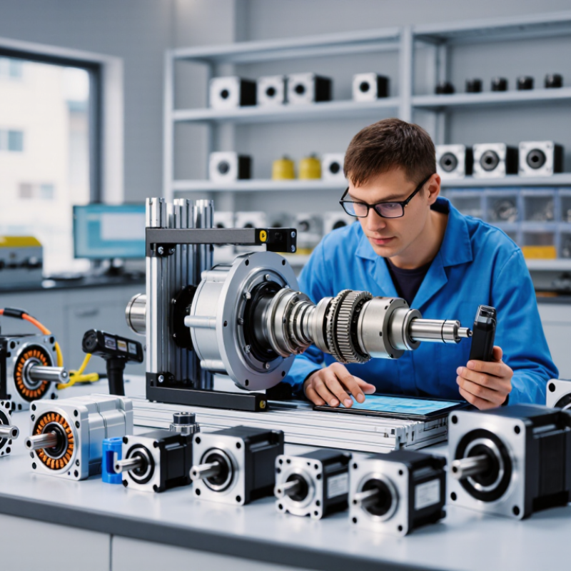
How to Choose the Right Robotic Gear Motor?

Define the Role and Operating Requirements of the Robot

How to Choose the Right Robotic Gear Motor?

Define the Role and Operating Requirements of the Robot

Start by defining what the robot must do, not which motor looks powerful. A warehouse robot needs steady wheel movement, accurate stopping, and long operating hours. A small inspection robot may need quiet motion and precise control instead. Write down the robot’s total mass, wheel diameter, travel speed, slope angle, and expected payload. These details determine the required torque and output speed.

Measure real working conditions. A robot climbing a ramp faces greater resistance than one moving across a smooth floor. Calculate rolling resistance, incline force, and acceleration demand before selecting the gearbox. Add a practical safety margin, often between 1.5 and 2 times the calculated torque. Do not rely only on stall torque. Continuous torque, thermal performance, duty cycle, and motor current matter during daily operation.

Consider the environment carefully.

Dust, moisture, vibration, and temperature can shorten service life. Backlash may affect robotic arms, while excessive noise can disturb indoor inspection tasks. Battery voltage must also match the motor controller and wiring limits. In testing, I have seen motors fail because the design considered peak force but ignored heat buildup. That mistake is easy to repeat. Prototype the drive system with the real wheels, surface, payload, and battery. Then check speed, current draw, temperature, and stopping accuracy after repeated cycles.

Match Motor Torque, Speed, and Gear Ratio to the Application

How to Choose the Right Robotic Gear Motor?

Match Motor Torque, Speed, and Gear Ratio to the Application

Choosing a robotic gear motor starts with the load, not the motor label. Measure the required force, wheel radius, and acceleration. For a wheeled robot, torque roughly equals force multiplied by wheel radius. Add friction, slopes, and a safety factor of 1.5 to 2. A neat calculation can still mislead when the floor surface changes.

Speed must match the robot’s real movement. A higher gear ratio increases output torque but reduces output speed. For example, a 20:1 ratio may provide strong lifting power, yet the robot could move too slowly for tracking tasks. Estimate the target wheel speed, then check whether the motor can reach it under load. Do not rely only on no-load speed.

Gear efficiency and operating time also matter. Continuous lifting creates heat, even when the motor appears powerful enough. Check the duty cycle, startup current, shaft load, and whether the mechanism can back-drive the motor. In practical testing, record speed and current with the actual battery and payload. I have seen designs pass bench tests but struggle on ramps. That is a useful warning. Leave space for real-world variation, because perfect assumptions rarely survive the first prototype.

How to Choose the Right Robotic Gear Motor? - Match Motor Torque, Speed, and Gear Ratio to the Application

Practical sizing guide based on typical robotic mechanisms. Values are representative design targets and should be verified against the actual load, duty cycle, acceleration, and safety requirements.
Robotic Application Typical Driven Load Required Output Speed Estimated Continuous Output Torque Recommended Peak Torque Capacity Typical Gear Ratio Range Suggested Motor Type Key Selection Consideration
Small wheeled mobile robot 1–5 kg total robot mass; two driven wheels with approximately 50–80 mm diameter 100–300 rpm at the wheel 0.10–0.35 N·m per wheel 0.25–0.90 N·m per wheel 20:1–60:1 Brushed DC or brushless DC gear motor with encoder Allow additional torque for carpet, ramps, starting friction, and uneven flooring.
Differential-drive service robot 10–30 kg total robot mass; 100–160 mm drive wheels 60–180 rpm at the wheel 0.80–2.50 N·m per wheel 2.00–6.00 N·m per wheel 30:1–100:1 Brushless DC gear motor with closed-loop speed control Check the motor continuously at low speed; high reduction ratios improve force but reduce free speed and efficiency.
Robotic arm shoulder or elbow joint 0.5–3 kg payload, depending on link length and joint orientation 10–60 rpm at the joint 5–25 N·m 10–50 N·m 50:1–200:1 Brushless servo motor with planetary or harmonic-style reduction Calculate gravity torque at the worst-case arm extension and include payload acceleration torque.
Pan-tilt camera or sensor head 0.2–2 kg payload; center of mass may be offset from the rotation axis 5–30 rpm at the axis 0.30–3.00 N·m 0.75–7.50 N·m 30:1–150:1 Stepper or brushless servo gear motor Prioritize low backlash, smooth motion, and holding torque; calculate torque from the offset center of mass.
Robotic gripper actuator 0.1–2 kg gripping load; leadscrew, rack, or linkage mechanism 10–100 rpm at the actuator 0.20–2.00 N·m 0.50–5.00 N·m 20:1–100:1 Brushed DC gear motor with encoder or compact brushless servo Match speed to required jaw travel and verify that the mechanism cannot back-drive under load.
Tracked inspection robot 20–80 kg total mass; high rolling resistance and frequent turning 30–120 rpm at the drive sprocket 3–15 N·m per drive side 8–35 N·m per drive side 50:1–150:1 High-torque brushless DC gear motor with encoder Use the worst terrain condition for sizing and confirm thermal performance during repeated starts and turns.
Small linear actuator 50–500 N axial force using a leadscrew or belt transmission 5–50 mm/s linear travel 0.50–5.00 N·m at the screw 1.00–12.00 N·m at the screw 10:1–100:1 DC or stepper gear motor with limit switches Convert linear force to screw torque using screw lead and efficiency; include end-stop and jam loads.
Autonomous mobile platform lift 10–100 kg lifting load using a screw, belt, or chain mechanism 5–40 rpm at the lifting mechanism 5–40 N·m 12–80 N·m 50:1–200:1 Brake-equipped brushless servo or geared DC motor Use a mechanical brake or self-locking transmission where an uncontrolled drop would create a hazard.
Design notes: Output torque should normally be selected with a service factor of approximately 1.5–2.0 above the calculated continuous requirement. For shock loads, abrupt reversals, or uncertain friction, a higher factor may be necessary. The ideal gear ratio is determined by the motor's efficient operating speed: Gear ratio ≈ motor operating speed ÷ required output speed. Theoretical output torque is approximately motor torque × gear ratio × gearbox efficiency. Gearbox efficiency varies by design, lubrication, ratio, speed, and load; do not assume 100%. Confirm peak torque duration, thermal limits, backlash, radial and axial load ratings, encoder resolution, and duty cycle before final selection.

Choose the Appropriate Motor, Gearbox, and Power Configuration

Choosing the right robotic gear motor starts with the mechanism, not the motor catalog. Measure the robot’s total mass, wheel radius, target speed, and working surface. A useful starting point is torque equals force multiplied by wheel radius. Add extra torque for slopes, acceleration, and small mechanical losses. Real robots rarely move under perfect laboratory conditions.

The gearbox determines the balance between speed and torque. A higher reduction ratio increases output torque but reduces speed and may increase backlash. Planetary, spur, and worm gearboxes also differ in efficiency, noise, durability, and holding behavior. For precise joints, check backlash and shaft stiffness carefully. For drive wheels, continuous torque matters more than a brief peak rating. My early designs focused too much on stall torque. That caused overheating during repeated starts.

Power configuration needs equal attention. Match the motor voltage with the controller and battery system. Check running current, stall current, duty cycle, and available cooling. A battery may support the rated voltage but still fail under sudden current demand. Leave wiring and protection margins. A motor that works on a test bench can struggle inside a sealed chassis.

Use encoders when position or speed feedback matters. Confirm mounting dimensions, shaft size, connector placement, and environmental exposure before ordering. Test the complete motor, gearbox, controller, and battery together. Measure temperature after realistic operation, not only after a short demonstration. Some calculations will be imperfect, so record actual results and revise the selection.

How to Choose the Right Robotic Gear Motor?

Compare the calculated output torque required by common robotic functions before selecting the motor, gearbox ratio, and power configuration.

The reference values are calculated using torque = force × lever arm. Recommended rated torque includes a 1.5× service factor for acceleration, friction, and load variation. Choose a gearbox that meets the rated torque while keeping the required output speed and motor power within the system limits.

Evaluate Size, Efficiency, Control, and Environmental Conditions

Choosing the right robotic gear motor starts with the machine’s actual workload. Measure the required torque, speed, duty cycle, and available mounting space. A motor that looks powerful may still overheat under repeated acceleration. I have seen compact prototypes fail because designers considered peak torque but ignored continuous torque. That mistake is easy to repeat.

Efficiency matters when robots run from batteries or operate for long shifts. Check the motor’s efficiency across its working speed, not only at the advertised maximum. Gear reduction can increase torque, but it may also introduce friction, noise, and backlash. Calculate energy loss through the gearbox and motor together. Leave a practical safety margin. Too much margin, however, can make the assembly unnecessarily heavy.

Control requirements deserve equal attention. Confirm whether the motor supports precise positioning, smooth speed changes, or rapid reversing. Match the encoder resolution and controller feedback to the robot’s accuracy needs. Then examine the environment closely. Dust, moisture, vibration, and temperature changes can shorten service life. A sealed housing may help, but it can also trap heat. Test the motor inside a chamber or mock-up that resembles real operating conditions. My own evaluations sometimes underestimate cable strain and startup loads, so I now inspect both after extended testing. Small details often reveal larger design weaknesses.

Verify Compatibility, Reliability, and Long-Term Maintenance Needs

Choosing the Right Robotic Gear Motor

Choosing a robotic gear motor begins with compatibility, not advertised torque. Check supply voltage, continuous current, peak current, shaft diameter, mounting holes, and gearbox orientation. Compare the motor’s rated speed with the robot’s actual load profile. A motor that moves a light arm quickly may overheat while lifting a gripper. Measure stall torque carefully. Do not treat it as a normal operating target. Include a practical safety margin for sudden starts, misalignment, and uneven loads.

Reliability depends on more than metal gears. Review duty cycle, operating temperature, dust exposure, vibration, and expected noise. Inspect the gearbox for backlash, seal quality, bearing support, and accessible fasteners. In workshop testing, recording temperature after repeated cycles often reveals problems that short demonstrations hide. A cool motor during one movement proves very little. It may still fail after an hour.

Long-term maintenance should be planned before installation. Ask how often lubrication requires inspection and whether replacement parts remain available. Leave enough space around the motor for cleaning, cable replacement, and torque checks. Monitor current, vibration, and unusual clicking during routine service. These small signals can reveal worn gears early. I would also document the original noise and backlash, because memory is unreliable. A spreadsheet helps, but it cannot replace a careful physical inspection.

FAQS

What should I define before choosing a robotic gear motor?

Define the robot’s mass, wheel diameter, speed, slope angle, and payload. These details determine torque and output speed.

Why should real working conditions guide motor selection?

Ramps, rough floors, and sudden starts increase resistance. Test with real wheels, surfaces, payloads, and batteries.

How much torque safety margin is practical?

A margin of 1.5 to 2 times calculated torque is often practical. The exact value still needs testing.

Is stall torque enough for selecting a gear motor?

No. Check continuous torque, peak current, heat, duty cycle, and daily operating conditions.

Which electrical details require compatibility checks?

Match supply voltage, controller limits, wiring capacity, continuous current, and peak current.

What gearbox features affect robotic performance?

Backlash, seal quality, bearing support, shaft size, mounting holes, and gearbox orientation all matter.

How can I detect overheating problems?

Record motor temperature after repeated cycles. A cool motor during one movement proves very little.

What environmental conditions can shorten service life?

Dust, moisture, vibration, and extreme temperatures can damage gears, bearings, seals, and electrical parts.

How should long-term maintenance be planned?

Leave space for cleaning, cable replacement, lubrication checks, and torque inspections. Keep replacement parts practical.

What early warning signs suggest gear wear?

Watch for rising current, vibration, unusual clicking, increased noise, and growing backlash. Document baseline conditions.

Conclusion

Choosing the right Robotic Gear Motor begins with understanding the robot’s role, movement pattern, payload, duty cycle, and operating environment. These factors determine the required torque, speed, positioning accuracy, and gear ratio. A motor should provide sufficient starting and continuous torque without unnecessary oversizing, while the gearbox should deliver the appropriate balance between speed reduction, force multiplication, efficiency, and backlash control. Selecting the correct motor type, gearbox structure, and power configuration is also essential for achieving stable and reliable operation.

Beyond basic performance, consider the motor’s physical size, energy efficiency, control method, heat generation, noise, and resistance to dust, moisture, vibration, or temperature changes. Electrical and mechanical compatibility with the robot’s controller, mounting system, and transmission components must be verified before installation. Finally, evaluate expected service life, lubrication requirements, inspection procedures, replacement accessibility, and overall maintenance demands. A careful comparison of these factors helps ensure that the Robotic Gear Motor delivers consistent performance, dependable motion, and long-term value throughout the robot’s working life.

Amelia

Amelia

Amelia is a seasoned marketing professional with a wealth of expertise in our company’s core offerings. With an unwavering passion for driving growth and innovation, she plays a pivotal role in shaping our marketing strategies and enhancing brand visibility. A key aspect of her responsibilities......