Noco tech Motor Noco tech Motor

What Is a Hydraulic Motor and How Does It Work?

Time:2026-09-28 Author:Sophia
0%

A Hydraulic Motor turns pressurized fluid into rotary motion. The principle is simple. A pump sends oil through the motor; internal gears, vanes, or pistons convert flow and pressure into torque at the output shaft. Picture a loader’s wheel turning slowly under a heavy bucket: the motor must deliver useful torque while handling heat, leakage, and changing loads. The basic idea is tidy. Real machines are not.

Grand View Research’s hydraulic motors market report estimated the global market at about USD 11.7 billion in 2023 and projected continued growth through 2030. Market estimates are not performance guarantees, but they signal the technology’s continuing role in construction, agriculture, and industrial equipment. For selecting a motor, the numbers that matter on the machine are operating pressure, flow rate, displacement, speed, torque, and efficiency—not market growth alone.

Fluid-power author Anthony Esposito describes hydraulic motors as “rotary actuators that convert hydraulic energy into mechanical energy.” That definition captures the central function, though it leaves out the engineering judgment behind a reliable installation. Too little flow can slow the shaft; excessive pressure can raise component stress and fluid temperature. This article explains the main motor types, how they create rotation, and how to assess their performance. It also considers trade-offs, because the highest torque rating is not automatically the right choice. Check the manufacturer’s specifications and operating limits before applying any general rule.
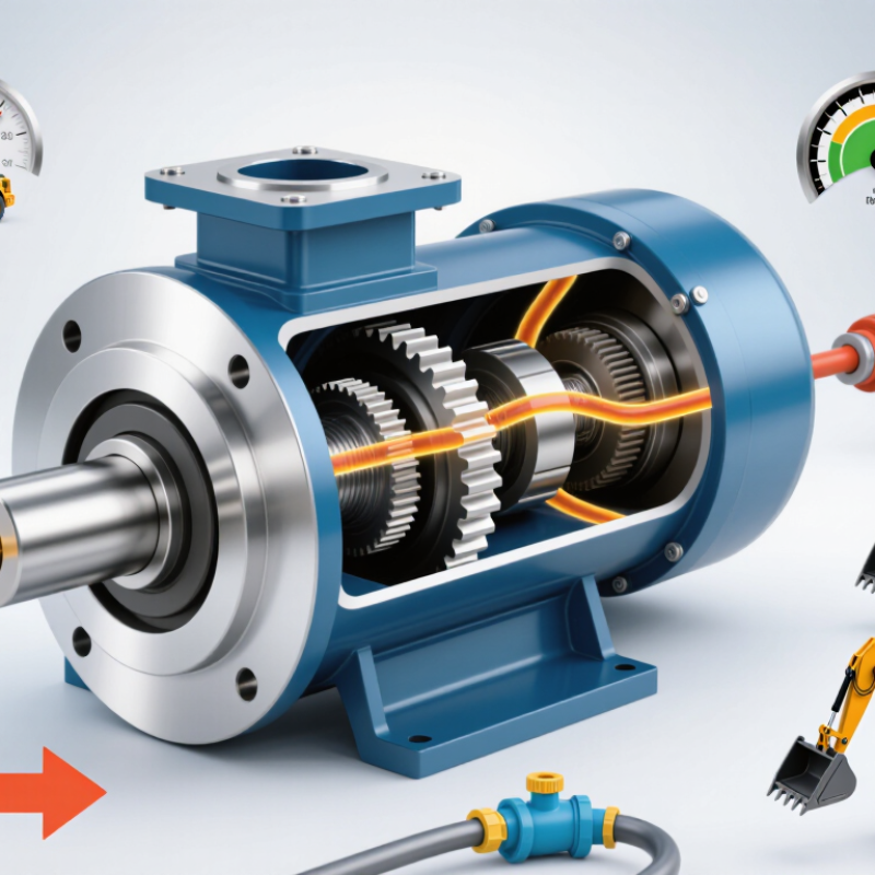
What Is a Hydraulic Motor and How Does It Work?

What a Hydraulic Motor Is and Its Role in a Hydraulic System

A hydraulic motor is a rotary actuator that converts hydraulic energy into mechanical rotation. It receives pressurized fluid from a pump and turns that energy into torque at a shaft. The shaft can drive wheels, a conveyor, a winch, or another rotating load. A motor is not the pump: the pump moves fluid, while the motor uses its flow and pressure to create motion. That distinction matters.

Inside the motor, fluid acts on internal parts such as gears, vanes, or a piston assembly. The design determines how the motor produces rotation, but the basic principle is similar. Pressure creates force, and moving fluid sustains movement. Flow rate largely affects speed; pressure and motor displacement influence available torque. These relationships are useful, but real performance also depends on load, fluid temperature, and internal leakage.

The motor is one part of a working hydraulic circuit. Hoses or pipes carry fluid from the pump, control valves direct it, and a return path sends it back to the reservoir. A relief valve can limit excessive pressure, while filters help reduce contamination that may wear close-fitting components. In practical setups, the motor must match the load and operating speed. An undersized motor may struggle under heavy loads; an oversized one can add cost and consume space. Even a well-chosen motor may feel sluggish if the fluid is too hot or the system is poorly maintained.

Main Components and Their Functions

A hydraulic motor turns pressurized fluid into rotary motion. Its housing contains the working parts and supports the shaft. Inside, gears, vanes, or pistons create moving chambers that take in oil and push it toward the outlet. The shaft transfers torque to the driven load. Bearings support the shaft, while seals limit leakage. Small leaks matter: they reduce output and can heat the fluid.

Port plates or internal valves direct flow through the motor. Their timing affects smooth rotation and torque. ISO 4409:2019 specifies steady-state tests for motor flow, speed, torque, leakage, and efficiency. For example, a motor with 50 cm³ displacement per revolution at 160 bar has about 127 Nm of theoretical torque, calculated from pressure and displacement. Actual torque is lower because of friction and leakage. That gap deserves attention.

In a piston motor, a rotating cylinder block carries pistons that press against an angled plate. The angle helps determine displacement. In a gear motor, meshing gears carry fluid around the housing; simpler, but often noisier. The details vary. A technician checking a sluggish motor should inspect fluid condition, inlet pressure, seals, and shaft load—not just the motor body. I have seen diagnosis stop too early at the component. That can miss the real restriction.

How Hydraulic Pressure Produces Rotary Motion

A hydraulic motor turns fluid energy into shaft rotation. Pressurized oil enters sealed chambers and pushes against vanes, gears, or pistons. That force creates torque. As the internal parts move, they carry the shaft around. The return fluid exits at lower pressure. Simple in principle. Less tidy in practice. Internal leakage, friction, and oil temperature reduce the motion available at the shaft.

Motor displacement sets how much fluid is needed for each revolution. Flow largely governs speed; pressure difference and displacement govern torque. In an ideal model, torque equals pressure difference multiplied by displacement, divided by 2π. Real motors fall short because of mechanical and volumetric losses. The U.S. Department of Energy’s 2006 report, Improving Pumping System Performance, estimates that pumping systems use nearly 20% of global electrical energy demand, with some industrial plants spending 25–50% of their energy on pumping. Those figures describe pumping systems broadly, not hydraulic motors alone, but they show why matching flow and pressure matters.

Consider a compact motor turning a conveyor roller. More flow can increase its speed, while a heavier load usually demands greater pressure and torque. If the load suddenly catches, pressure may rise sharply. Relief valves help limit that spike, though they do not erase heat or wasted energy. A gauge and a temperature reading tell only part of the story. In field work, leakage and changing oil viscosity can complicate the neat textbook picture.

What Is a Hydraulic Motor and How Does It Work? — How Hydraulic Pressure Produces Rotary Motion
A hydraulic motor converts pressurized fluid flow into rotary motion. Pressure creates torque, while the rate of fluid flow primarily determines rotational speed.
Dimension How It Works Relevant Data or Relationship Practical Note
Energy conversion Pressurized hydraulic fluid enters the motor and acts on internal moving surfaces, producing shaft rotation. Hydraulic input power is approximately pressure difference × flow rate. The motor needs both a pressure difference across its ports and fluid flow.
Pressure difference The inlet-to-outlet pressure difference pushes against gears, vanes, or pistons inside the motor. A pressure difference of 16 MPa equals 160 bar, or about 2,320 psi. Greater pressure difference generally produces greater torque, within the motor’s design limits.
Flow rate and speed Incoming fluid repeatedly fills the motor’s working chambers, turning its rotating group and shaft. Approximate speed is proportional to flow rate and inversely proportional to displacement per revolution. Leakage and other losses mean actual speed differs from the ideal value.
Displacement Displacement is the theoretical volume of fluid needed for one shaft revolution. For example, 100 cm³/rev is 0.1 L/rev. At the same flow rate, a larger displacement generally gives lower speed and higher torque capacity.
Torque relationship Pressure acting on the motor’s displacement creates turning force at the shaft. Theoretical torque: T = Δp × Vd ÷ (2π). With 16 MPa and 100 cm³/rev, theoretical torque is about 255 N·m. Actual output torque is lower because of mechanical losses and depends on the motor design and operating condition.
Illustrative flow example The fluid volume required per revolution can be multiplied by rotational speed to estimate ideal flow. At 100 cm³/rev and 1,200 rpm, ideal flow is 120 L/min. Actual inlet flow is typically higher because of internal leakage; this is an illustrative calculation, not a product rating.
Gear motor Fluid pressure turns meshing gears; fluid is carried around the housing and discharged at the outlet. A positive-displacement motor type with a relatively simple rotating group. Often used where a compact, straightforward drive is suitable; operating limits vary by design.
Vane motor Sliding vanes form chambers against a cam ring; pressure on the vanes creates rotation. Chamber volume changes as the rotor turns within the housing. Performance and suitability depend on pressure, speed, fluid, and the specific motor construction.
Piston motor Pressurized fluid moves pistons; their motion against an angled swash plate or bent axis turns the shaft. Available in fixed- and variable-displacement designs. Variable displacement can change the relationship between flow, speed, and torque.
Direction and control Changing which port receives pressurized fluid can reverse rotation in motors designed for reversible operation. A directional control valve commonly routes flow to the selected motor port. Reversibility and allowable operating conditions should be confirmed for the motor and hydraulic circuit.
Key takeaway: Pressure difference is the main determinant of torque, while fluid flow relative to motor displacement is the main determinant of speed. Actual performance is affected by volumetric and mechanical losses.

Common Hydraulic Motor Designs

Hydraulic motors convert pressurized fluid into rotary motion, but their internal designs affect speed, torque, efficiency, and maintenance. Gear motors use meshing gears to carry oil through the housing. They are compact and mechanically simple, making them useful for steady, general-purpose work. Their clearances matter: worn surfaces can increase internal leakage and reduce performance.

Vane motors use sliding vanes that move against a shaped ring as the rotor turns. They can run smoothly, which helps when equipment needs controlled motion. However, vane wear and oil cleanliness deserve attention. A small amount of contamination can affect clearances. Useful, but not forgiving.

Piston motors arrange pistons either around a central axis or radially around a shaft. Axial-piston designs often suit higher-pressure systems and variable-speed demands; radial-piston designs can deliver strong torque at low speeds. Actual performance depends on displacement, operating pressure, fluid temperature, and installation. A specification sheet can make selection look straightforward, but cold oil, changing loads, and limited maintenance access complicate the decision. Compare the motor’s operating range with the machine’s real duty cycle, not just its peak rating.

Operating Characteristics and Typical Applications

A hydraulic motor converts pressurized fluid into rotary motion. Its operating characteristics depend mainly on flow, pressure difference, and displacement. At a fixed displacement, flow largely determines speed, while pressure difference determines available torque. In practice, this relationship is not perfectly tidy. Leakage, friction, and fluid temperature reduce output, and efficiency changes with load. Real systems can be messy. A motor that slows under load may face insufficient flow, excessive resistance, or worn internal parts.

These characteristics shape where motors work best. Compact, high-torque units can turn wheels or tracks on mobile equipment, while steady rotation suits conveyors, mixers, and agricultural machinery. Winches need strong starting torque to move heavy loads, often at controlled speeds. The right motor depends on the duty cycle, required torque, operating speed, and available hydraulic supply. Engineers also consider heat and noise; these details are easy to overlook during early selection.

Tips: Match displacement and pressure ratings to the actual load, not just peak demand. Keep fluid clean, check for leaks, and monitor operating temperature. If performance changes, measure flow and pressure before replacing components. Safety guards matter around rotating shafts.

FAQS

How does a hydraulic motor create rotation?

Pressurized oil pushes against internal gears, vanes, or pistons. Their movement turns the shaft. Simple in principle.

What controls motor speed and torque?

Flow largely controls speed. Pressure difference and displacement determine available torque. Leakage and friction reduce actual output.

Why can actual torque be lower than the theoretical value?

Friction, internal leakage, and other losses reduce shaft torque. A 50 cm³ motor at 160 bar has about 127 Nm of theoretical torque, not guaranteed output.

What parts help control flow and prevent leakage?

Internal valves or port plates direct oil through the motor. Seals limit leakage, while bearings support the shaft. Small leaks matter.

Why might a motor slow down under load?

It may have insufficient flow, excessive resistance, worn parts, or a supply restriction. Check the system, not just the motor.

What should a technician inspect first?

Check fluid condition, inlet pressure, seals, shaft load, and operating temperature. Measure flow and pressure before replacing components.

How do hydraulic motors suit different machines?

Compact, high-torque motors can turn wheels or tracks. Steady rotation suits conveyors, mixers, and agricultural machinery. Duty matters.

What happens when a load suddenly catches?

Pressure can rise sharply. A relief valve helps limit the spike, but heat and wasted energy can remain.

How can operators reduce avoidable wear?

Keep fluid clean, check for leaks, and monitor temperature. Use guards around rotating shafts. Easy to overlook.

Conclusion

A Hydraulic Motor is a device that converts pressurized hydraulic fluid into rotary motion, allowing a hydraulic system to drive wheels, drums, winches, and other machinery. It works alongside a pump, valves, and fluid lines: the pump supplies pressurized fluid, while valves control its direction and flow. Inside the motor, components such as a housing, rotating assembly, shaft, and seals guide the fluid and transfer its force to the output shaft.

As pressurized fluid enters the motor, it acts on internal surfaces and creates a turning force, or torque. The motor’s speed generally depends on fluid flow, while its torque is influenced by pressure and design. Common designs include gear, vane, and piston motors, each suited to different combinations of speed, power, and operating conditions. Hydraulic motors are valued for delivering strong output in a compact form and are used in applications such as construction equipment, agricultural machinery, industrial systems, and mobile equipment.

Sophia

Sophia

Sophia is a dedicated marketing professional with an exceptional depth of knowledge about her company's products and services. With a keen understanding of market trends and customer needs, she crafts insightful blog posts that not only inform but also engage readers, enriching the company’s online......